
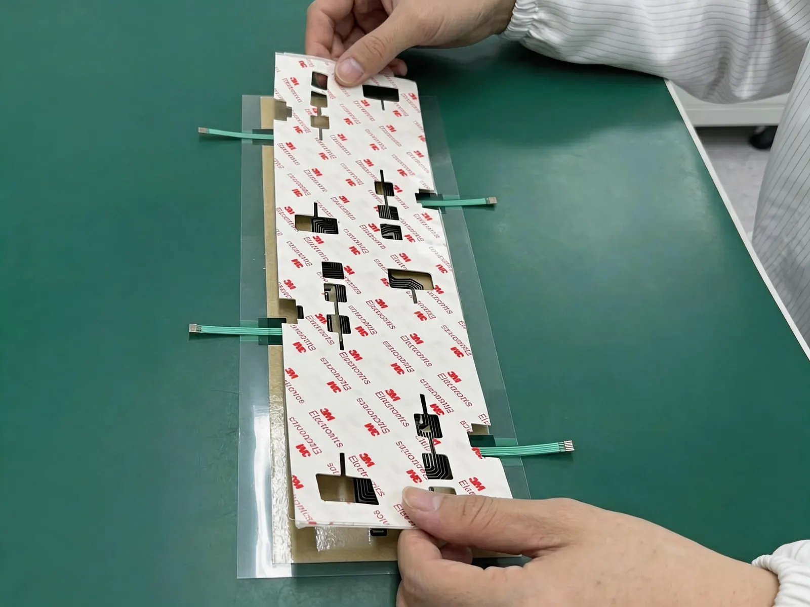
A membrane switch tail must reach the PCB connector without being pulled tight, trapped by the housing or bent at an unsuitable location. Confirm the tail construction and the mating connector together. A silver-printed PET tail and a copper FPC tail need separate construction and termination checks.
For the keypad, tail and connector to be reviewed together, see Baoshengda's custom membrane switch construction options. Send the enclosure route as well as the front artwork.
Choose the tail exit from the housing layout
Before fixing the exit position, check:
- Where does the tail run inside the enclosure, and where will it bend?
- Could a screw boss, rib, board edge or cover pinch it during assembly?
- Must the cover lift for servicing while the tail remains connected?
Walk through the assembly sequence with the intended housing and a sample. Show the exit position from a defined datum on the drawing.
Measure the routed length and service movement
Measure the installed route from the keypad exit to the connector's mating position. Include the space needed for insertion, strain relief and any agreed service movement. Check where the spare length will sit when the cover is closed.
There is no universal extra length or bend radius for all membrane switch tails. Epec's membrane switch tail bending note, published January 15, 2014, explains that circuit construction and bend location affect the choice. Its dimensions describe its design guidance. They are not Baoshengda production limits.
Ask the supplier to confirm the bend location and radius for the proposed stack. With the sample routed and the housing closed, check electrical continuity. A flat bench check alone does not verify the installed route.
Match the stiffener to the connector drawing
Where the connector requires a reinforced mating end, specify the stiffener material, thickness, length and position. Check the total mating thickness against the connector manufacturer's drawing, including the tail layers and adhesive.
A stiffener at the contact area does not resolve a sharp enclosure edge or a pull load at the panel exit. Review those areas separately. Do not assume that every connector needs the same reinforcement or accepts the same tail thickness.
Select a termination for the actual tail construction
- For a ZIF or LIF connector, confirm the exact part number, contact side, pitch, position count, mating dimensions and operating instructions. The connector family name is not enough to establish compatibility.
- For a fitted socket or crimped terminal, agree the terminal system, housing and tail construction before sampling. Check how it will be supported and disconnected in the enclosure.
- Do not specify direct hand-soldering as a default termination for a silver-printed PET tail. If a soldered connection is required, have the supplier confirm a suitable circuit construction and joining process first.
The Hirose FH34(S) operation and design precautions, pages 7 and 8, illustrate why the exact connector matters: they specify insertion orientation, space for straight insertion and removal, and use of the specified mating dimensions. These are instructions for that connector series, not universal dimensions for a membrane switch tail.
Confirm pin functions and contact orientation
List each pin function, including any LED, shield or ground connections. Mark pin 1, the viewing direction and the contact side on both the tail drawing and the PCB connector reference.
An incorrect orientation or pin mapping can prevent the intended functions from working. Confirm the mapping electrically on the assembled sample. A tail photograph cannot replace that check.
What to send before quotation
- A dimensioned tail exit position and the enclosure route.
- Total routed length and any required service movement.
- Tail construction, width, pin count and labeled pin functions.
- The PCB connector part number and current drawing, if available.
- Required stiffener details or mating thickness to be confirmed.
- Bend locations and how the panel will be assembled and serviced.
If the connector has not been selected, send the available space and interface requirements. Agree the mating details before approving the sample for repeat production.
For a tail and connector review, send the route sketch and connector drawing, or identify the mating details still to be confirmed.
Need help reviewing a structure?
Send your drawing, photos, application, and quantity. Baoshengda can help check the structure before sampling.
Send Drawing for Quote