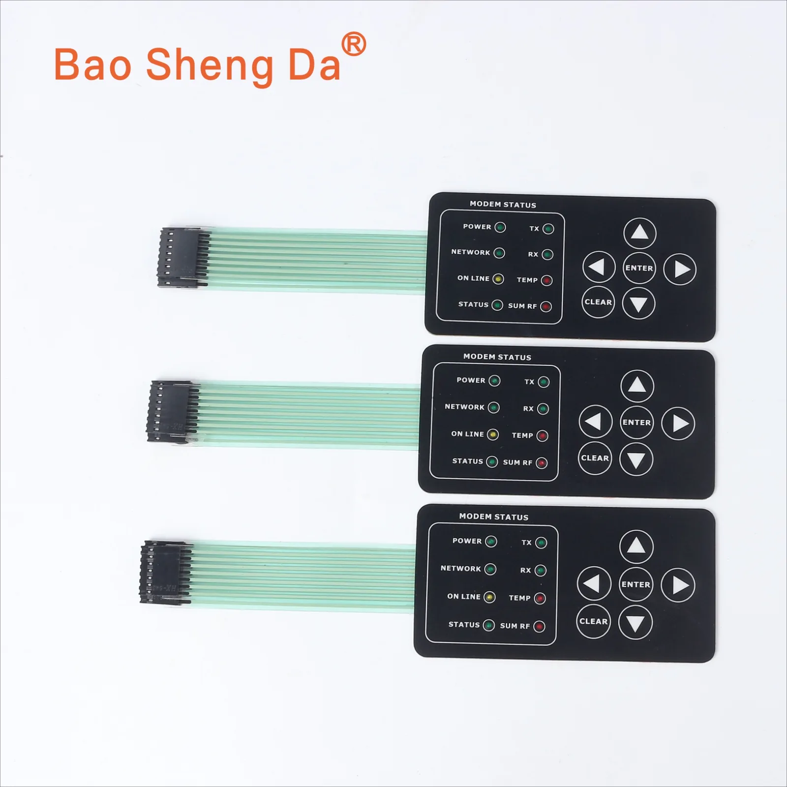
Custom membrane switches and keypads made to your drawing. We review the overlay, key structure, circuit, tail and mounting details against your equipment.
Lower printed circuitContact pattern and output-tail route
Rear adhesiveBonding area matched to the equipment housing
Housing side
A common printed-contact example, not a fixed production stack. Dome, FPC or PCB choices can change the construction. Confirm the layers, tail and connector on the approved drawing and sample.Keypad and film layers shown for construction reference. The layer diagram is an example, not a specification for this photographed keypad.
Layer, material and connection details
Graphic OverlayThe top visual and touch surface. It can be made with PET, PC or other suitable films, and printed with custom colors, icons, windows, logos and functional markings.
Overlay AdhesiveUsed to bond the graphic overlay to the switch structure. Adhesive type can be selected based on the housing material and working environment.
Metal Dome or Tactile LayerOptional tactile feedback layer. Metal domes can provide clear key feedback and improve user operation confidence.
Spacer LayerCreates the separation between the upper and lower circuit layers, helping control actuation force and switch travel.
Printed Circuit LayerCan be designed with silver ink, carbon ink, FPC or PCB depending on the electrical, mechanical and assembly requirements.
Rear Adhesive LayerUsed to mount the membrane switch onto the equipment housing, panel or plastic enclosure.
Connector / TailThe connection interface can be customized according to the customer’s electronic control board and assembly requirements.
Is a custom membrane switch the right interface for this project?
A membrane switch suits equipment that needs a thin, drawing-specific control surface with printed legends, keys and a flexible connection. The housing must support the key and adhesive stack. Define the functions, electrical interface, cleaning exposure and expected volume before approving a sample.
We review the overlay, printed or FPC circuit, spacer, tactile parts, adhesive, backlight and tail against your drawing. Controller logic, enclosure-level sealing, end-product safety and regulatory approval remain with the equipment maker. Photos can start the discussion; repeat production should follow an approved drawing and a sample checked in the intended housing.
If you only need the printed face, windows and adhesive backing, choose a PET or PC graphic overlay. Use this page for a membrane-switch assembly with switching contacts and a circuit, and include the key functions and connection details in your request.
Good fit when
The key layout, legends and circuit route are project-specific.
A thin front surface or wipe-clean interface is preferred.
The housing can support the key and adhesive stack.
Send for first review
Overall dimensions and key or function map.
Artwork plus tail, pinout and connector details.
Housing, environment, prototype quantity and demand estimate.
Approve before repeat production
Mounted key feel and circuit function.
Overlay registration, tail route and connector fit.
Adhesive contact and project-defined sealing checks.
A membrane switch combines a printed overlay, circuit, spacer, adhesive and switching contacts in a thin control surface. Key shapes, legends, windows, tail and mounting adhesive are specified for the equipment.
Sealing, cleaning resistance and electrical performance depend on the finished construction and the tests agreed for the application. Review those requirements with the housing and controller interface, rather than treating the keypad as a stand-alone part.
Construction options to confirm
ItemOptions / Description
Product TypeMembrane switch or keypad assembly; overlay and front-panel scope reviewed separately
Overlay MaterialPET or PC; other film choices reviewed against the application
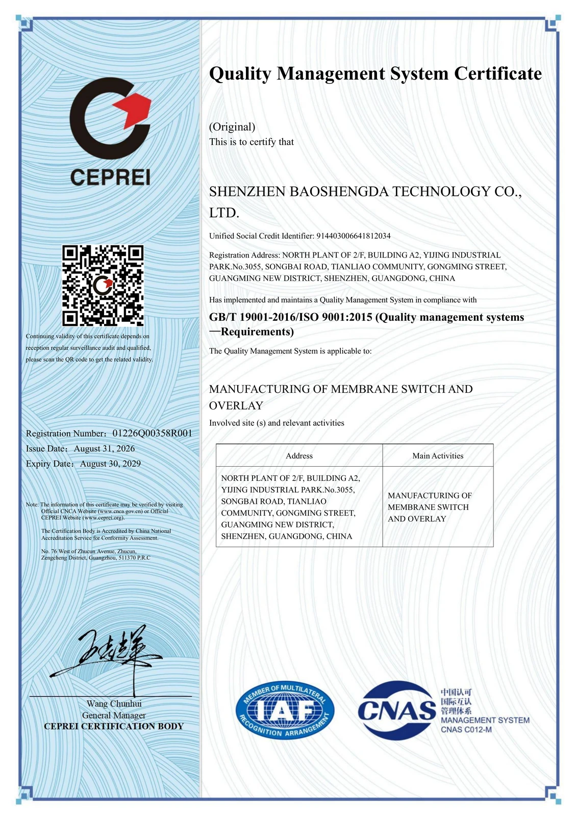
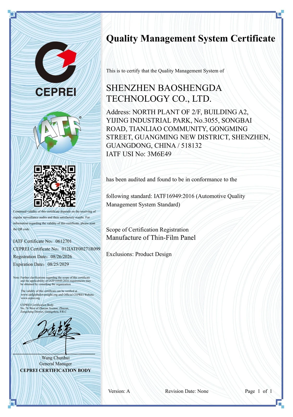
Quality documentsISO 9001 and IATF 16949 certificate scopes are linked on this page; material documentation is reviewed for the selected construction
Final specifications depend on product structure, material selection, application environment and customer design requirements.
Customization Options
Specify the options that affect the fit, electrical connection and appearance of your part. Availability and verification depend on the chosen materials and approved drawing.
Graphic and Appearance
Custom color, logo, icons and symbols
Transparent or semi-transparent display windows
Dead-front effect
Matte, glossy or textured surface
Selective embossing and key shaping
Electrical and Functional Design
Tactile or non-tactile keys
Metal dome design
Printed circuit, FPC circuit or PCB integration
LED / LGF / EL backlighting
EMI shielding option
Custom connector and tail design
Mechanical and Assembly Design
Custom outline shape
Different adhesive systems
Tail exit direction
Housing fit design
Waterproof edge sealing
Gasket or sealing structure
Environmental Requirements
Waterproof and dustproof design
Chemical cleaning resistance
UV resistance
Anti-scratch surface
High and low temperature application support
Outdoor or harsh environment protection
Applications
Membrane-switch layouts can be reviewed for different equipment interfaces. Each application has its own mounting, electrical and environmental requirements.
Medical Equipment
For a medical control panel, specify the cleaning method, graphic windows, key functions and required end-product approvals before selecting the keypad structure.
Industrial Control
Industrial controllers and instruments often need a defined tail route, glove-use key feel and a mounting surface that supports the switch stack.
Automotive Electronics
Vehicle-interface projects need drawing-controlled appearance, electrical connections and tests appropriate to the installation. The keypad is a component, not a complete controller.
Security and Access Control
For an access terminal or alarm keypad, review the enclosure opening, tail exit, outdoor exposure and sealing target as one assembly.
Home Appliances and Smart Devices
Appliance interfaces may combine printed legends, indicator windows and a thin key layer. Define cleaning exposure and housing support for the actual product.
Instrumentation and Test Equipment
For test instruments and handheld equipment, confirm key spacing, window visibility and connector clearance on the intended housing.
Production checks and project testing
Visual inspection of printed overlays at the factory.
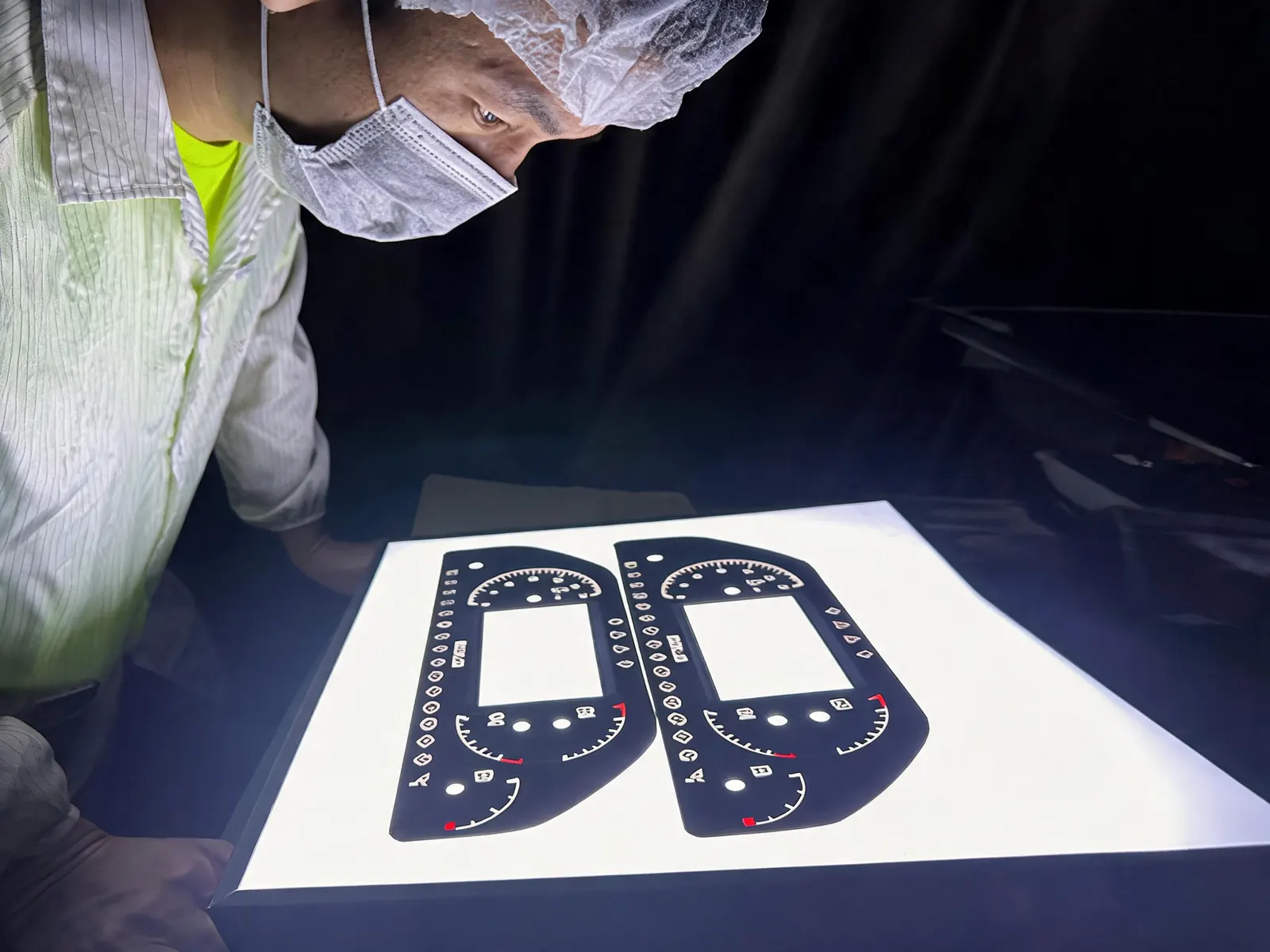
Agree the inspection and test plan for the actual part and operating environment. The photograph shows a visual check; it does not demonstrate every test listed below.
Appearance inspection
Dimensional inspection
Key function testing
Key life testing
Adhesion and bonding review
Color and transparency inspection
Electrical continuity testing
High and low temperature evaluation
Salt spray testing where applicable
Constant temperature and humidity testing where applicable
Material compliance support such as RoHS / SGS reports where applicable
For automotive, medical, outdoor or industrial use, define acceptance criteria and required reports before sampling. A listed test is not a claim that this specific part has passed it.
See the production process and certificates
Review the screen-printing photograph and read the certificate scopes and validity dates. Part requirements are agreed separately for each drawing.
Screen printing at BaoshengdaPrinted graphics are one part of the finished assembly. Review the artwork, windows and mounting requirements together.
Quality-system certificates
Open each certificate to read its manufacturing scope and validity dates.
Certification applies to the scope stated in each document. Your part's dimensions, materials and acceptance checks are confirmed for the project.
From drawing review to repeat production
Review the inputsCheck the artwork, key functions, housing surface, tail route and connector against the current drawing.
Agree the sample checksConfirm appearance, mounted fit, key feel and circuit function on the equipment before approving the revision.
Control the revisionUse the approved drawing, artwork and test requirements as the reference for repeat production.
For the company timeline and certificate scope, see Baoshengda's history and the documents above.
Low-volume membrane keypad prototypes
For a low-volume keypad project, separate the sample quantity from the expected production demand. Send the available drawings or sample information. The quotation can then cover the overlay, switching circuit, tactile elements, tail, connector and mounting adhesive.
Starting a new design? Use the drawing and quotation checklist below. Replacing an existing keypad? Send front and rear photos and identify the features that must stay unchanged; see the existing-part review.
What should the prototype quotation separate?
Sample quantity and scopeState how many samples you need and whether they are for appearance, fit or functional checks. Ask us to confirm the minimum order quantity for this construction.
Tooling and setupAsk us to itemize any non-recurring engineering (NRE), tooling or setup charges separately from the sample-unit and repeat-production prices. Confirm what each charge covers and how a drawing revision could affect it.
Repeat productionShare the expected order quantities and annual demand separately. A sample request does not need to be presented as a confirmed production order.
Schedule and approvalGive your target date. Confirm the sample schedule after the drawing, materials, connector and required checks have been reviewed.
Before sampling, agree the drawing and artwork revision, key functions, connector pinout, housing fit and required checks. Ask which inspection or test records can be supplied for your construction, and agree their scope and format. Before repeat production, the buyer should check the sample in the intended equipment and approve it against the agreed acceptance criteria.
For key-force approval, check more than one key position on more than one physical sample, then repeat critical checks after mounting.
No complete drawing yet? Start with photos, dimensions and a short description of the application. Attachments are optional for the initial request.
What Should Buyers Define for an OEM Terminal Keypad?
An OEM terminal-keypad RFQ should define the key layout and functions, tactile structure, indicators, circuit tail, connector, overlay and adhesive, enclosure fit, prototype quantity and expected annual demand. A photo or old sample helps explain the appearance, but the latest drawing and electrical requirements should control the quotation.
RFQ decisionEvidence to send or confirm
Key layout and functionOverall size, key count, key positions, legends and a simple pin or function map.
Tactile responseMetal-dome or non-tactile requirement, target key feel and any embossing or spacer constraints.
Indicators and windowsLED quantity and position, icon or window appearance, light-blocking areas and viewing conditions.
Tail and connectorTail exit direction, usable length, pin count, contact side, connector pitch and first-bend clearance.
Overlay and mountingArtwork, material and finish, housing drawing, adhesive landing area, cleaning method and indoor or outdoor environment.
Approval and volumePrototype quantity, expected annual demand and the dimensional, visual, electrical and mounted-fit checks used to approve the sample.
Can you quote a replacement for an existing membrane keypad?
Baoshengda can review an existing keypad, drawing or sample for custom manufacture. A matching outline is only the starting point: key functions, tail pinout, contact side, connector, mounting thickness and housing fit also need to match the equipment.
Send front and rear photos, the available drawing revision and the features that must stay unchanged. If the electrical details are incomplete, identify what needs confirmation rather than assuming the original and replacement are interchangeable. Approve the sample on the intended equipment before repeat production.
Send what you have; a complete drawing is useful but not required for an initial review:
2D drawing or 3D structure file
Artwork file, color requirements or Pantone code
Product size and thickness requirements
Circuit diagram or functional key layout
Tactile or non-tactile key requirement
Connector type and tail direction
Backlight requirement, if any
Waterproof or sealing requirement
Application environment
Estimated annual quantity
Sample or existing product photos
If the design is still being developed, send the application, approximate dimensions and photos. We can identify the missing details before a formal quotation.
FAQ
What information do you need to make a custom membrane switch?
We usually need the product drawing, artwork, circuit layout, key function requirement, connector type, application environment and estimated quantity. If you do not have complete files yet, you can send samples or photos for initial review.
Can you make waterproof membrane switches?
Yes. We can design sealed structures and waterproof solutions based on project requirements. The final waterproof level depends on the product structure, material selection, tail exit design and assembly method.
Can the membrane switch include backlighting?
Yes. We can support LED, LGF, EL and customized backlighting designs. Backlighting can be used for key areas, icons, display windows and dead-front effects.
What materials are commonly used for the graphic overlay?
PET and PC are commonly used. The final material depends on the required durability, surface finish, transparency, printing effect, operating environment and cost target.
Can you make tactile membrane switches?
Yes. We can design tactile membrane switches using metal domes or other tactile structures. Actuation force and key feel can be adjusted according to the user experience requirement.
Do you support FPC or PCB integration?
Yes. Depending on the design, we can support printed circuit, FPC circuit or PCB-based integration to match the customer’s electronic control system.
What industries do you mainly serve?
Our membrane switch solutions are used in medical equipment, industrial control, automotive electronics, instruments, security devices, home appliances and smart electronic products.
Can you help optimize my membrane switch design?
Yes. We can review your drawing, material selection, adhesive structure, tail direction, key layout, sealing requirement and manufacturing feasibility before sampling.
Related HMI components
Related component families include:
HMI front-panel components
Membrane switches and keypads
FSR pressure sensors
Flexible heating films
Graphic overlays
Related products and engineering guides
A membrane switch can form the input layer of a larger front-panel assembly. Review the overlay, FPC circuit, backlighting and sealing structure against your equipment design. Baoshengda supplies the specified components or assembly; the equipment maker defines controller behavior and end-product approval.
Send a drawing, sample or photos. Include the key functions, tail or connector, housing details and expected quantity if available. We will review the scope before quoting.