
For a thin single-key membrane switch, ask for the installed stack drawing before approving a sample. Define the panel support, adhesive surfaces, permitted height and connector access. A flat-looking button can still conflict with a housing rib, a curved mounting surface or the space needed to connect its tail.
This guide uses a historical patent drawing to explain what to ask. The sample-review steps below are our engineering recommendations, not test results reported in the patent.
The layer arrangement in CN220456274U
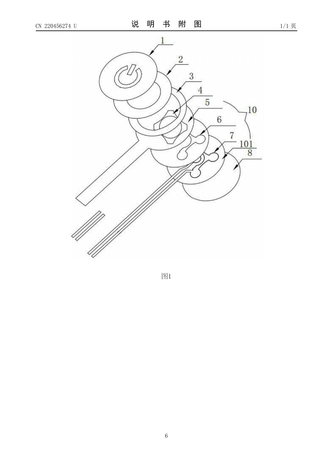
Baoshengda's thin single-key switch document, CN220456274U, is a Chinese utility-model grant publication dated 2024-02-06. Claims 1–6 describe a panel and circuit substrate, printed silver, carbon and insulation layers, a surrounding water-protection ring, a resilient metal dome and adhesive layers. Claim 2 specifies a PET panel. Figure 1 shows the exploded arrangement.
The image above reproduces the document's complete drawing page. Its labels identify the panel (1), first adhesive (2), ring (3), tactile dome (4), insulation (5), carbon (6), silver (7), rear adhesive (8), circuit layer (10) and substrate (101). It is an illustration of the document, not a photograph of a supplied assembly or a drawing to scale. Open the complete original drawing page at full resolution.

This arrangement gives the buyer separate items to review: the surface being pressed, the supporting structure, the space occupied by the switching layers and the route out to the connector. The document does not provide a finished height and tolerance for your enclosure.
Define the installed stack from a common datum
Start with a section through the button center and the actual mounting panel. Mark which face is the assembly datum. Then identify what belongs to the switch supplier and what belongs to the enclosure. A drawing that measures only the loose switch leaves the panel recess, mounting adhesive and support undefined.
Use an approval record with these fields:
- Height: finished stack and tolerance at the button, plus the permitted projection above the housing. State whether a protective film or release liner is excluded from the measurement.
- Support: the surface beneath the active area and any relief required around it. Record panel flatness and assembly features that could press on the switch before the user touches it.
- Bonding surfaces: housing material, finish and cleaning method; identify the adhesive footprint and any unbonded zones on the drawing. Confirm a specific adhesive grade with the supplier rather than accepting a brand name alone.
- Connector access: tail exit, connector orientation and room for assembly or replacement. Check these with the housing closed as well as open.
Keep unknown dimensions marked as open questions. An enclosure photo or a rough section can start the discussion; neither needs to be presented as a released manufacturing drawing.
Review feel on the support that will be used
A loose sample can help identify the legend and connector, but approve the press action on a representative support. Ask the supplier which surface and fixture were used when describing the feel. If the intended enclosure is not ready, identify the substitute support and retain that difference in the sample record.
Agree where the button will be pressed, including any off-center positions the user is likely to reach. Check whether the overlay returns freely and whether the enclosure creates unintended contact. Have the equipment team record electrical closure and release using its agreed circuit and acceptance criteria. A finger's impression of a click does not establish the electrical result.
For a useful sample comparison, change one assembly condition at a time. Record the sample revision, support, adhesive condition and connector arrangement. If a sample feels different after mounting, investigate the changed assembly before attributing the difference to the dome alone. These checks are proposed review steps, not performance data for CN220456274U.
Keep document claims separate from acceptance evidence
Paragraph [0034] describes a 2.54 mm black-housing terminal connector. That number is not the switch's finished stack height. Request the actual connector drawing and mating-part details before assigning a pin spacing or compatibility requirement.
The ring and adhesive arrangement is a reason to ask how the proposed assembly handles its intended exposure. It does not establish an IP rating for a complete enclosure. Specify the exposure and acceptance method separately if water resistance matters. Do not use the exploded drawing to approve a sealing result.
The document also makes lifetime and production-benefit assertions. It does not supply a complete test protocol or measured results supporting a purchasing acceptance decision. We have not verified the patent's current legal status or its implementation in a particular supplied product. A dated grant publication establishes the document type and publication event; it does not establish either of those current facts.
Send the fit question before preparing every drawing
For custom membrane switch stack and sample review, identify the single button's job and the part of the assembly that is uncertain. A connector clearance question needs a different first reply from an adhesive or installed-feel question.
You can request a thin single-key switch review with an existing photo or drawing if available, the intended use, an approximate quantity and the unresolved fit or sample question. A complete production drawing is not required to make first contact. Mark unknown dimensions so they can be discussed rather than silently assumed.
Before approving the sample, ask for a revision-controlled stack drawing, identified connector and a record of the conditions used for the agreed checks. Keep the equipment's final validation separate from the component sample decision.
Need help reviewing a structure?
Send your drawing, photos, application, and quantity. Baoshengda can help check the structure before sampling.
Send Drawing for Quote